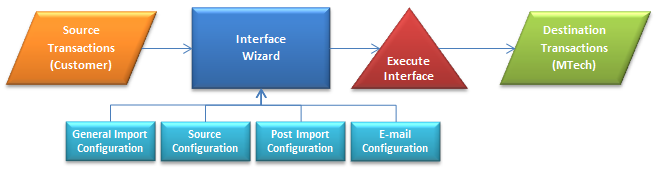
Interface Import
The details outlined in this document represent the requirements to
import data from another system to MTech. This document summarizes the
base concept for all exports, however each export will be uniquely defined
based on the requirements. The assigned Project Manager can provide sample
interface requirements for many types of export interfaces.
The following procedures and options are covered in this document:
Create an Interface
The following sections are defined in the Create Interface section of
this document:
Definition
- In Admin>System>Interfaces,
select Interfaces.
- Select
 to
create a new interface.
to
create a new interface.
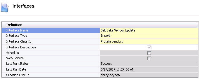
- Enter the Interface
Name for interface. Alphanumeric,
50 characters maximum.
- Select the Interface
Type as `Import`.
- Select the Interface
Class ID as required for the import.
- Interface Description
is an optional location to enter a description for the import to identify
the data that is being imported as well as any other details related
to the import.
- The Schedule
flag will be selected if there is a schedule associated with the interface.
If the flag is not selected, then there is no schedule assigned and
the interface must be run manually.
- Web Service
is currently not an available option.
- Last Run Status
displays the status after the interface was last executed. If 'NA'
appears as the status, the interface has never been run. Otherwise,
the field will display 'Success' or 'Failed'.
- Last Run Date
indicates the date that the interface was last executed. The default
date of 11/30/1899 will be displayed until the interface is run for
the first time.
- Creation User
ID displays the user that created the interface.
- The Prompts
section is intended to be used for Web Service which is currently
not an option.
- Click the
 in the menu bar to complete the remaining requirements for the import
interface.
in the menu bar to complete the remaining requirements for the import
interface.
General Import Configuration
- Selecting the Wizard option will open the General
Import Configuration.
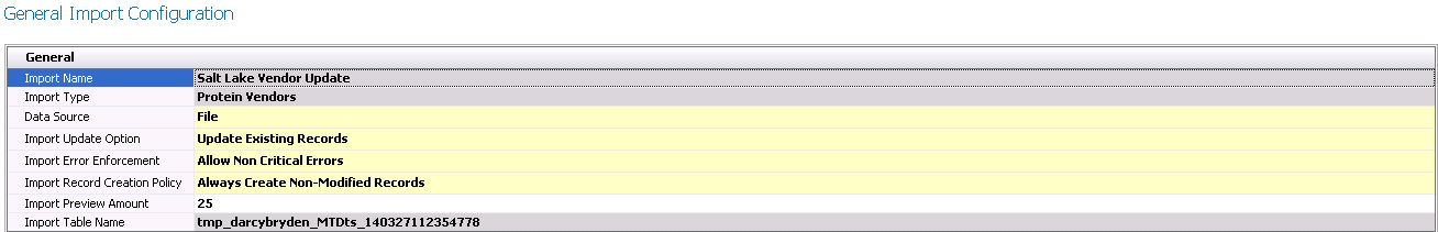
- Import Name
and Import Type will
be derived from the initial screen.
- Select the Data
Source. The current options available are Database, File, FTP,
HTTP and OData.
- Select the required Import
Update Option. Options available will be:
- Create New
Always - all source records will be treated as new records
- Log Duplicate
Records - duplicate records will be logged as errors
- Update Existing
Records - existing records will be updated with the source
data
- Select the required Import
Error Enforcement that controls how the errors affect the completion
of the import. Options available are:
- Allow Non-Critical
Errors - errors that are considered non-critical will allow
the import to execute and provide warnings.
- None
- there is no enforcement on errors.
- Strict
- all errors will stop the import of data
- The Import Record
Creation Policy determines how the import engine handles the
creation of records. Options available are:
- Always Create
Non-Modified Records - always creates records even if all
of the default values were not modified.
- None
- does not create any records.
- Remove Non-Modified
Records - removes record from import if all of the default
values were not modified.
- Enter the number of lines that will be viewed
in the export preview in the Import
Preview Amount. This data will be viewed to validate that the
source data appears correct.
- Select the required option for Last
Run Status Option. This option determines what the status will
be if no records are exported. The options available are NA or Failed.
- Click Next to move to the Source
Configuration screen.
Source Configuration
Depending on the Data Source, the Source Configuration screen will vary
based on the requirements. Click on the required Data Source type to view
the required configuration.
Database
- In the Destination
Connection, select the ellipse to open the Connection Builder.
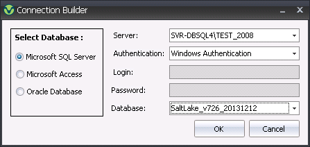
- Select the Database
type. Options will be Microsoft SQL Server, Microsoft Access or
Oracle Database.
- Select the required Server.
- Select the Authentication.
Options will be Windows Authentication or SQL Server Authentication.
- If required, enter the Login
and Password.
- Select the required Database.
- Click OK
- Define the query required for the source data.
- Click Next to close the query builder.
- Select the Database Date Format for the source
data.
- Select Preview Data to view the source data.
- Click Next to move to the Source
Field Properties.
File
- In the Source Configuration screen, select the
Import File Format. Options
will be Delimited File or XML Files.
- Select the File Mode. This option is only required
for File and FTP data sources. Options are as follows:
- Multiple
Files - imports from all files matching the given file
pattern.
- None
- does not import from any files.
- Single
- imports from a single file source.
- Select the Data
Server is the data source is set to Database. Other data sources
do not require the field to be selected.
- Select the File
Name for the import.
- In the File Date
Format, select the date format for the source import data.
- Click on the ellipse in the Intermediate
SQL field if additional SQL statements must be run against
the data being imported to change or modify fields.
- Depending on the selected Import File Format,
there will be a tab with fields to enter the required details.
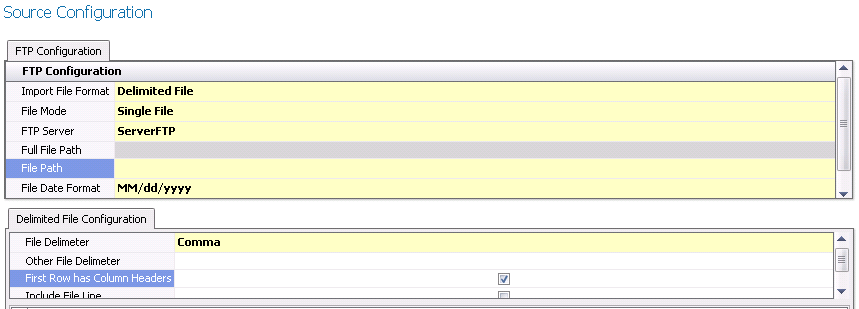
Delimited
File:
Select the File
Delimiter. Options available are Comma, Custom, Pipe, Semicolon
or Tab.
If Custom is selected as the File Delimiter, enter the character
in the Other File Delimiter.
Select First
Row Has Column Headers if the first row of the file is
defined as headers.
Select Include File Line if the
source file line is to be added to the intermediate table.
Click Preview Data to view the
source data.
XML
File:
Enter the XML statement in the
XML Configuration File.
Click on Next to
move to Source Field Properties.
FTP
Prior to using FTP as the required Destination Type, the FTP server
must be set up in Admin>System>Servers.
- Select the Import
File Format. Options will be Delimited File or XML.
- Select the File
Mode. Options will be Single File, None or
- Select the FTP
Server that will receive the data.
- Select the Directory
Path Name for the data to be exported.
- Select the File
Name that will receive the export data.
- The File Extension
will default from the selected file.
- Enter the Date
Format to Append the current date and time to the file. An
example would be: YYYY-MM-DD_hh_mm_ss.
- Full Path Preview
provides the user with the complete destination location for the export
data.
- Export to File
Format indicates the type of file that will receive the export
data. Options are CSV, Fixed Field, Pipe, Tab or xml.
- Select Output
Column Headers if the data headers are to be exported to the
export file. Do not select the option if the headers are not required.
- Select Do Not
Create File If No Records if the file is not to be created
where no data exists. Leave field blank if the file is always to be
created.
- Select Next to move to E-Mail
Configuration or Finish to complete the interface definition if
e-mail is not required.
HTTP
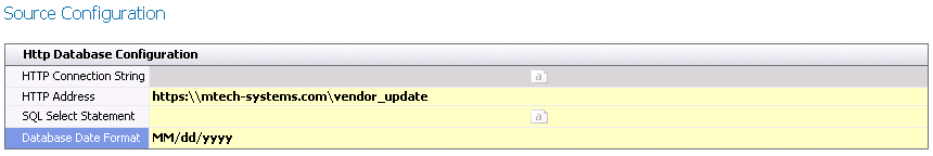
- Enter the HTTP
Connection String in the text field associated with the import.
- Enter the HTTP
Address for the import data.
- In the SQL Select
Statement, select the text box and define the
SQL statement to extract the data for the import.
- Select the required Database
Date Format from the drop-down box.
- Select Next to move to E-Mail
Configuration or Finish to complete the interface definition if
e-mail is not required.
OData
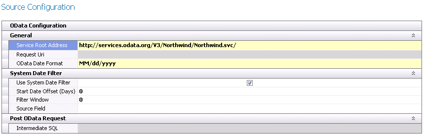
- In the Service
Root Address field, enter the web address for
the source data.
- Request Uri
defines the request that OData uses to query the resources.
- In the OData
Date Format, select the required date format of the data that
is being imported.
- Select the Use
System Date Filter if it is required to define a date filter
based on the current system date.
- Start Date Offset
(Days) defines the number of days to offset the system date
to filter the data for the import. This value can be positive or negative.
- Filter Window
represents the number of days to add to the Start Date as computed
by the Start Date Offset.
- In the Source
Field, select the field that represents the data filter.
In the Intermediate
SQL, enter the SQL statement to update the source data with
any required options.
Select Next to move to E-Mail
Configuration or Finish to complete the interface definition if
e-mail is not required.
Source Field Properties
Source Field Properties sets the default properties from the source
file. The user has the option to modify the defaults as required.
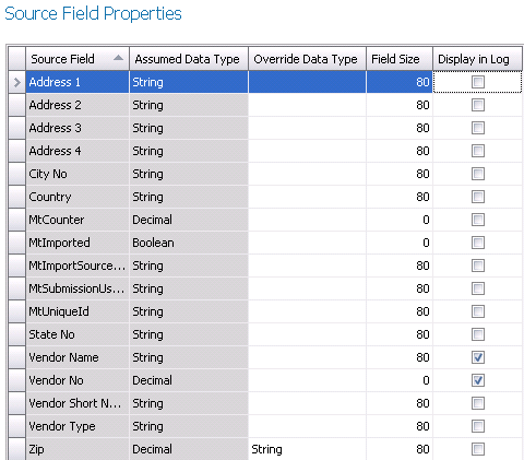
- Source Field
displays the name of the field in the source file.
- Assumed Data Type is the derived field type based on the
source file.
- Override Data
Type allows the user to modify the Assumed Data Type. Click
on the drop-down to select the required data type.
- Field Size
is based on the Assumed Data Type. If the data type is overridden,
the Field Size may require modification.
- Check any fields that are required to be displayed
in the error logs.
- Click Next to move to Field
Mapping.
Field Mapping
Field Mapping maps the source file to the destination tables.
- Select the Table Name for the mapping. Several
tables may be displayed for the fields to be mapped correctly.
- The Required
flag will default as selected for any fields that must be mapped.
If the Required flag is not selected, the field mapping is optional.
- Data Type
represents the data type of the destination field in MTech.
- Destination Field
is the name of the field in MTech.
- In the Source
Field, select the corresponding field for the Destination Field.
If the field requires additional specifications, the Derived Field
can be used. This may be used to define a specific value for a field
or define an enum that may exist in the system for certain fields.
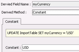
- Click on the Derived
Field if required to define the parameters.
| Constant |
SQL Lookup |
 |
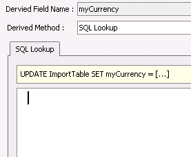 |
- The Derived Field Name will automatically
be set to the Destination Field prefixed by 'my' so that it is
identified as a derived field.
- Select the
Derived Method. Options
will be:
- Constant
- sets a constant value to a field
- None
- no derived value.
- SQL Lookup
- uses a SQL statement to create the derived field.
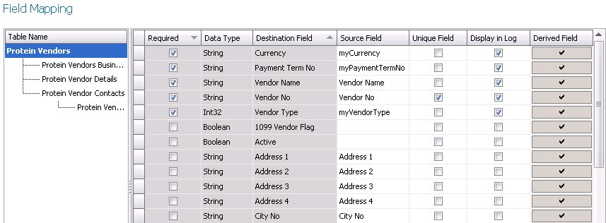
- At least one field must be set as Unique
Field. Multiple fields may be required to identify the records.
- Select the Display
in Log for the fields that are required to be displayed in
the error logs.
- Click Next to move to Intermediate
Results Preview.
Intermediate Results Preview
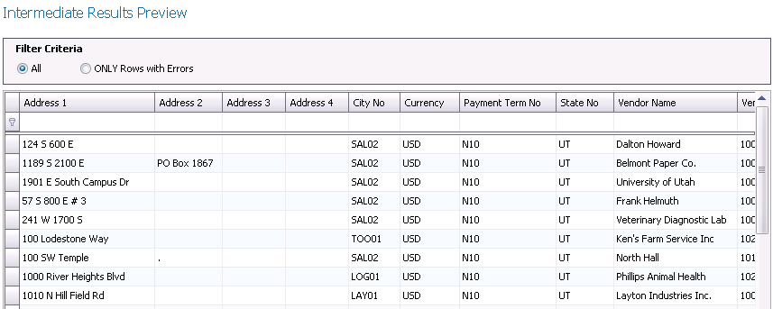
- In the Filter
Criteria, select the option to view All data or Only Rows with
errors.
- Click Preview
Intermediate Results to review the source data.
- Click Next to move to Results
Preview.
Results Preview
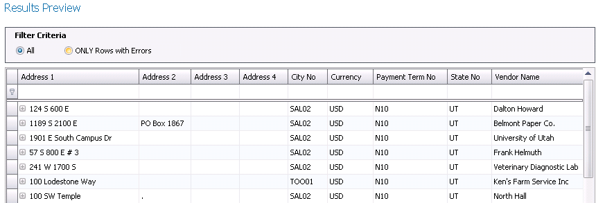
- In the Filter
Criteria, select the option to view All data or Only Rows with
errors.
- Click Results
Preview to review the data in the destination view.
- Click Next to move to Post
Import Configuration.
Post Import Configuration
There are three sections to configure related to Post Import.
General

- Post Process
SQL is used to update the SQL after the records are imported.
Click on the ellipse to define the SQL statement. This option will
not execute from the wizard.
- Select Use Source
Connection String for the Post Process SQL. If the option is
not selected, the process will use the current connection string.
This option must be left unchecked if the Data Source is set to File.
- Select Use Transaction
Scope for Post Process if required. Leave unchecked if it is
not required.
Error File
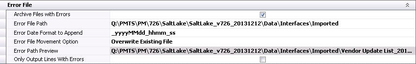
- If error files are to be archived, select Archive Files with Errors and the
files will be moved to the user defined location. If the error files
are not to be archived, do not select the option and the error logs
will be saved in the source location.
- If the Archive Files with Errors option is selected,
specify the path to save the error logs in Error
File Path.
- In the Error
Date Format to Append, enter the format of the date that is
to be added to the error log file name. An example would be '_yyyymmdd_hhmm_ss'.
- In the Error
File Movement Option, select the action to perform for the
error log after the import has been run. The options will be Append
to Existing File or Overwrite Existing File.
- Error Path Preview
displays the location where the error file will be saved and how the
file name will be displayed.
- The Only Output
Lines with Errors option is only available when Delimited File
is the selected source file type.
Completion File
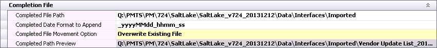
- Select the Completed File Path to move the source
file after it is completed.
- In the Completed
Date Format to Append, enter the format of the date that is
to be added to the source file after it has been imported. An example
would be '_yyyymmdd_hhmm_ss'.
- Select the Completed File Movement Option to determine
the action on the source file after it has been imported. Options
are Append to Existing File, Do Nothing, Overwrite Existing File.
- Completed Path
Preview displays the location where the source data file will
be saved and how the file name will be displayed.
- Click Next to move to E-Mail
Configuration.
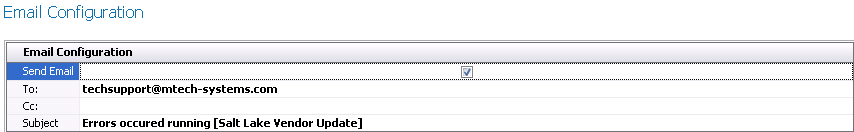
E-Mail Configuration
- Select the Send
E-Mail option if there is to be an e-mail sent when errors
occur in the process.
- In the To:
field, enter the e-mail addresses that are to receive the e-mail separated
by a semi-colon.
- In the Cc:
field, enter the e-mail addresses that are to copied on the e-mail
separated by a semi-colon.
- The Subject
must be defined if the Send Email option is selected. If this is not
acceptable, enter the text that is to appear in the e-mail subject
line.
- Click Next or Finish to complete the wizard process.
Execute an Interface
The Execute Interface option runs the interface definition and imports
the data to MTech. Options for generating the interface are as follows:
- From Admin>System>Interfaces,
select the interface and right-click to select Execute Interface.
- From Admin>System>Interfaces,
select the interface and select Options>Execute Interface from
the tool bar.
- From Admin>System>Interfaces,
edit the interface and select Options>Execute Interface from the
tool bar.
Interface Error Logs
The Interface Error Logs provide details related to number of records
imported and specifies any errors that may be incurred during the import
process. There are two access the logs. The 'View Logs' option displays
all logs that have been generated from the interface. The 'View Last Log'
only displays the last generated log. Options for viewing the interface
logs are as follows:
- From Admin>System>Interfaces,
select the interface and right-click to select View Logs or View Last
Log.
- From Admin>System>Interfaces,
select the interface and select Options>View Logs or Options>View
Last Log from the tool bar.
- From Admin>System>Interfaces,
edit the interface and select Options>View Logs or Options>View
Last Log from the tool bar.
This will display the Import Error Log.
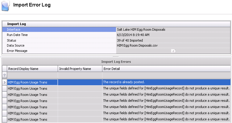
Import Log
- Interface
displays the name of the interface that has generated the error log.
- Run Date Time
indicates when the interface was executed.
- The Status
will display how many records were imported based on the total records.
- The Data Source
represents the name of the source file that contained the data.
- Error Message
will display any error messages that relate to the overall interface
configuration.
Import Log Errors
This section displays errors related to the actual data that is being
imported.
- Record Display
Name indicates the table record that the data is being imported.
- Invalid Property
Name will provide the details for any errors that are generated
from the interface.
- Error Detail
provides a description related to the error so that the user can determine
how to resolve.
Scheduling Interfaces
There is an option to schedule interfaces for those that are required
on a regular basis. Before the scheduler can be used, the Job Service
Scheduler must be installed. The following topics are covered in this
section:
Install Job Scheduler Service
- The user will be provided with a file for the
installer named MTechSystems.JobScheduler.Setup. msi.
- Double-click to start the installation process
and install in a folder dedicated to the installer. The job scheduler
will install as a Windows service called MT Job Schedule Service.
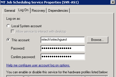
- Configure the Job Scheduler Service with a user
that has permissions to read and write from the import and export
folders. This can be accomplished by selecting the Log On tab in Service
Properties and use This Account option to define the user. A domain
service account may also be created for this purpose.
- Edit the MTechSystems.JobScheduler.Service.exe.config
file in the installation folder of the MT Job Scheduling Service (completed
in Step 1). Edit the datasource.default.connectionstring value to
match the values found in the mtech.cnn file.
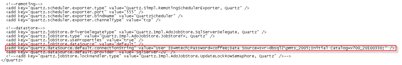
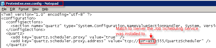
- Edit the Proteinexe.exe.config to reflect the
server:port specified from the MTechSystems.JobScheduler.Service.exe.config.
- Ensure that the Protein folder and subfolders
have read/write/modify permissions for all users that intend to use
the program.
Configure Scheduler
This section will demonstrate how to assign a schedule to the interface.
- To schedule a job, select the required job from
the index and right-click to select Schedule Job.
- This will launch the Job Scheduler Wizard for
the selected interface.
- If no triggers exist, select the Create
Trigger tab. In the Trigger field, enter a name for the schedule
trigger, such as Daily, Weekly, Hourly and select Create Trigger.
- If Triggers exist, click the Select
Trigger tab and select the required trigger for the interface.
- Click Next to move to the configuration of the
General details.
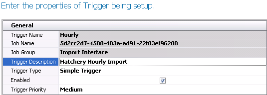
- Trigger Name
will default from the selected trigger as read-only.
- Job Name
will display the system code for the interface that is being scheduled.
- Job Group
will display the type of interface. The field will display Import
Group or Export Group depending on the type of the interface.
- In the Trigger
Description, enter a description for the schedule.
- Select one of the following options for Trigger Type.
- Cron Trigger
- used to schedule jobs that recur based on calendar-like notions.
- Simple Trigger
- used to schedule jobs that occur at a specific moment and recurring
in regular intervals.
- Enabled
will default to selected to indicate that the schedule will be executed.
Un-check the option if the schedule is no longer required to be run.
- Select the Trigger
Priority. Options will be High, Medium or Low.
- Select Next to move to Conditions. The Conditions
screen will be different for Cron Trigger
or Simple Trigger.
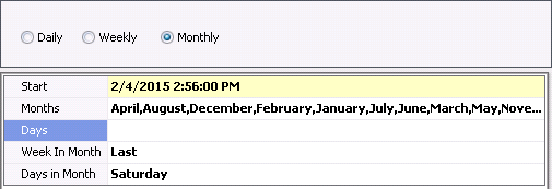
Cron Trigger
- Select the option for the schedule as Daily,
Weekly or Monthly. Depending on the selected option, the configuration
screen will appear with different options.
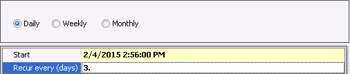
Daily
In the Start
Field, enter the start date and time for the schedule.
In the Recur
Every (Days), enter the number of days before the next schedule
runs.
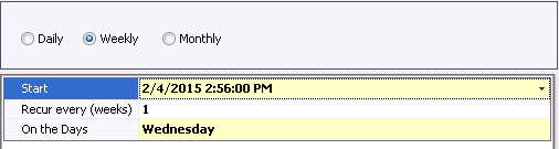
Weekly
- In the Start
field, enter the start date and time for the schedule.
- Enter the recurrence in the Recur
Every (weeks) field.
- In the On
the Days field, select the days that the day(s) of the
week that the schedule is to run.
Monthly
In the Start
field, enter the start date and time for the schedule.
Select the Months that the schedule is to run.
Days
allows the user to define the day of the month that the schedule will
run. For example, the schedule will run on the 15th day of the selected
month(s).
Week
In Month allows the user to define the week in the month that
the schedule will be run. Options are First, Second, Third, Fourth
or Last. Select Not Set if this option is not required.
Days
in Month allows the user to select the day in the month that
the schedule will be run. In the example below, the schedule will
run on the last Saturday of every month.
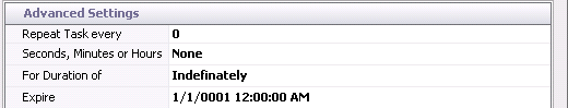
- In the Advanced Setting
section, set the Repeat Task Every
to '0' as it is not required for this feature.
- In the Advanced Setting
section, set the Repeat Task Every
to '0' as it is not required for this feature.
- Set the Seconds,
Minutes or Hours field to None as it is not required for this
option.
- Select the required
option For Duration of.
- Enter the date and
the time that the schedule will Expire.
Simple Trigger
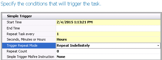
- Enter the Start
Time for the schedule.
- If there is a defined
End Time, enter the time in
this field, otherwise leave the field blank and the interface will
run continuously based on the other parameters.
- Enter the frequency
in the Repeat Task Every field.
- Select the time frame
in Seconds, Minutes or Hours
field.
- There are two options
in Trigger Repeat Mode. Repeat
Indefinitely indicates that the schedule will continue to be run to
infinity or until the schedule is disabled. Specified Count will run
the schedule a specified number of times.
- If the Trigger
Repeat Mode is set to Specified Count, enter the number of
times the schedule is to run. Otherwise, leave the default value of
'0'.
- Simple
Trigger Misfire Instruction determines what will happen if
the schedule cannot be run. None indicates that it will just run on
the next cycle. Trigger Now indicates that the schedule will continue
to determine if it can be run immediately after the initial schedule
cannot run.
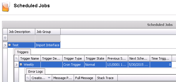
Scheduled Jobs
- Once the job schedule has been configured, the
schedules can be viewed in Admin>System>Jobs Scheduled.
- Select the required job and click on the child
grid to review the Triggers and Error Logs.